In this series of blog posts I will adventure into the field of precision timekeeping. Part one will explore how to interface a precision clock source to a computer. In future posts I will attempt to calibrate the clock source with NTP and measure it's performance.
What is a Crystal Oscillator?
Quartz crystals are electronic components that resonate at some particular frequency. They are used in computers to generate clock frequencies, both directly for the real time clock as well as reference inputs to chips that generate the high frequency clock signals needed for the CPU, memory and I/O buses.
What is an Oven Controlled Crystal Oscillator?
Like most electronic components, crystals are dependent on temperature. The rated frequency shifts slightly up or down depending on ambient temperature. This is undesirable for precision timekeeping. OCXOs compensate for this by putting the crystal in a temperature regulated heated can ("the oven").
Description of Hardware Used
 |
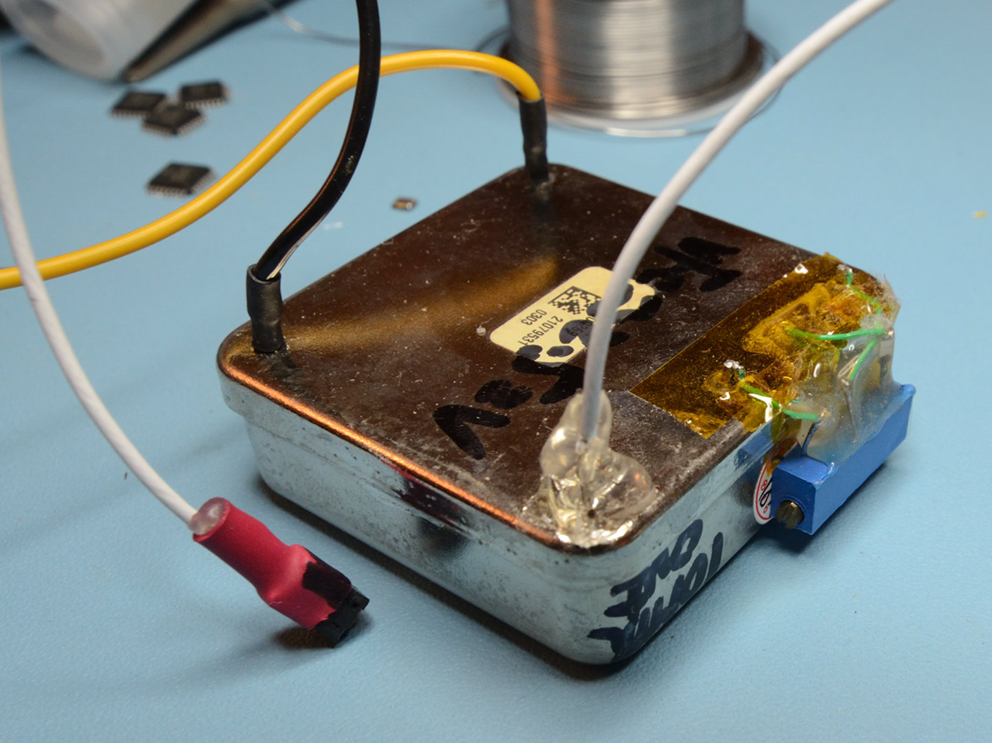
| Salvaged Trimble 65256 unit |
I purchased two of these used OCXOs from an Ebay listing a few years ago because I wanted to learn more about precision timekeeping. (But then for some reason I shelved them and forgot about them until now!) They are powered by a +12 V rail and generate a 50
Ω ±800 mV sine wave signal at 10 MHz. They contain an internal 2.5 V reference voltage which should be used by external circuitry to generate a calibration voltage.
 |
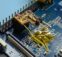
| Modified OCXO |
The modules arrived without any leads or calibration, so first I had to modify them. I glued a trim pot to the side of the can. Resistors, like crystals, also have temperature coefficients. I figured that since the oven is temperature controlled the resistor should maintain a reasonably constant temperature if glued directly to the lukewarm can. The idea then is that the trim pot can be used as a voltage divider to generate the calibration voltage. For the signal output I used some thin coaxial wire salvaged from a laptop WiFi antenna.
Connecting OCXOs to a Computer
The kernel timekeeping framework,
timecounter(9), makes it easy to hook up arbitrary digital counters and use them as a source for time. We could easily build a microcontroller circuit that counts the sine wave signal and feeds the counter serially into a
gpio(4) pin. But then we need a microcontroller and also we have to characterize and account for the latency and jitter of reading a GPIO pin.
 |
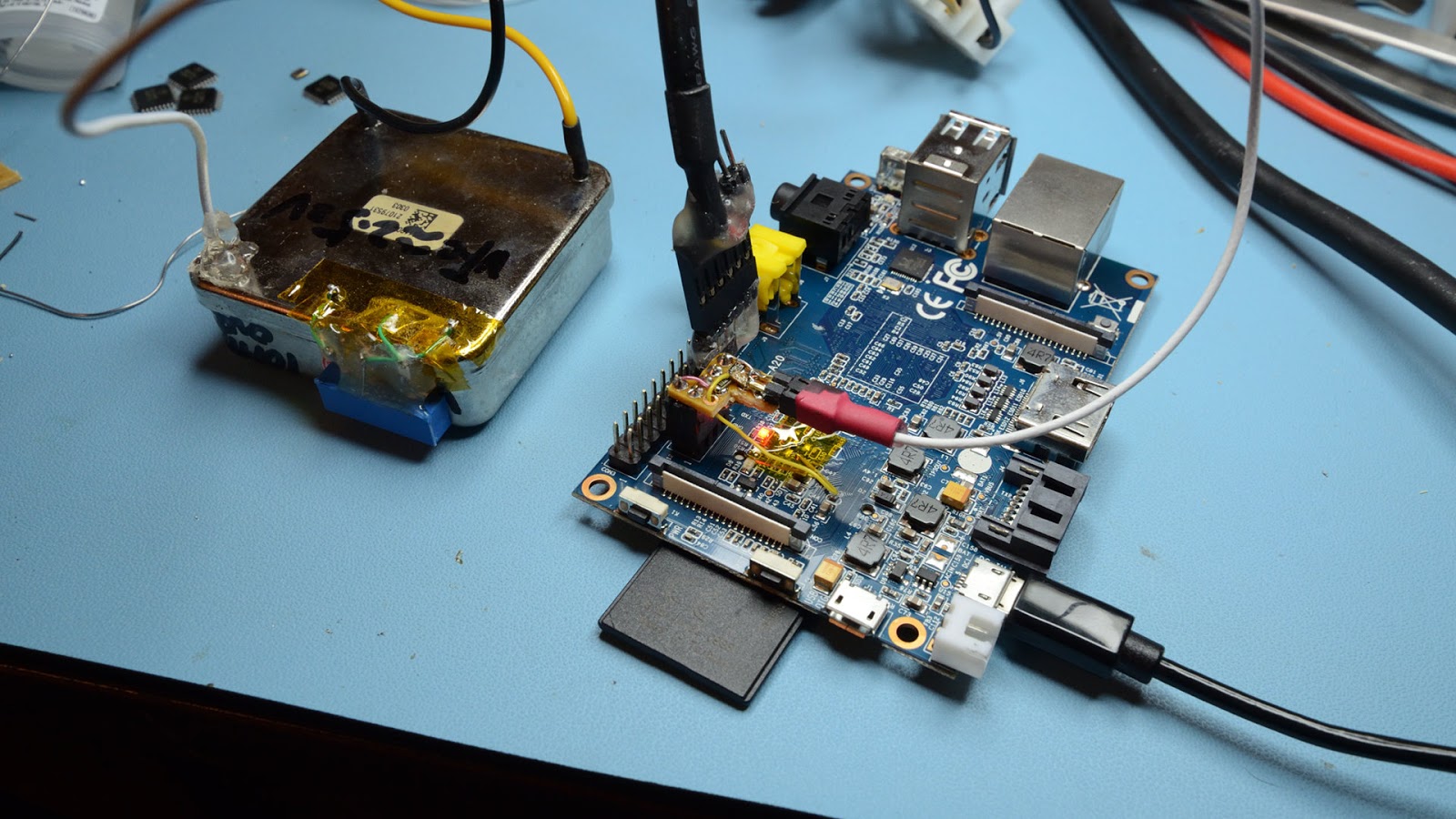
| Banana Pi M1 SBC |
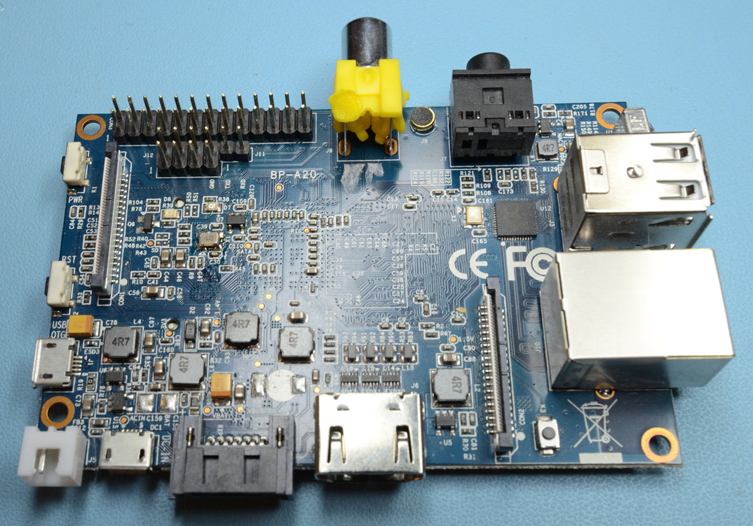
So, instead we will try to replace the computer's existing reference clock. The computer we will use is a
Banana Pi M1 SBC running
NetBSD/evbarm. The M1 uses an
Allwinner A20 SoC, designed to be used with a single 24 MHz reference clock, which is multiplied and divided to synthesize all the clock signals required by the board. Everything from the CPU to serial UARTs and the HDMI port is referenced to this clock. For example the CPU clock runs at 24 Mhz
× 38 = 912 MHz.
A problem is that our replacement reference clock runs at 10 MHz, not 24 MHz, so time will slow down by a factor of 10/24. The board itself doesn't really care or even know about this, but it becomes an issue when interfacing with the rest of the world. For example the serial UART baud rate will be wrong. Fortunately this can mostly be compensated for in software by reprogramming relevant clock multipliers.
How Clock Signals Are Generated On The M1 Board
 |
| Figure 1: Location of X24* pins on SoC |
The A20 SoC contains an internal PLL circuit. on the SoC there are two
pins
X24MI (clock input) and
X24MO (clock output), across which the SoC
expects a 24 MHz crystal to be connected (Figure 1).
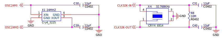
On the M1 board the crystals are connected according to Figure 2. The crystal is labeled
X1 on the board and is easy to locate visually (Figure 3).
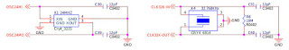 |
| Figure 2: M1 Oscillator schematic |
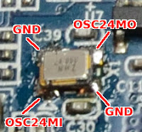 |
| Figure 3: X1 location and pins |
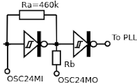 |
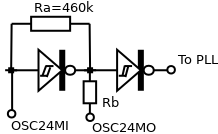
| Figure 4: simplified model of internal clock amp |
We don't know anything about how the clock amplifier circuit inside the SoC is designed, but a typical clock amplifier circuit looks something like figure 4 and for our purpose this simplified model serves fine. We need to desolder
X1 and adapt the 10 MHz signal to make it suitable to inject at
X24MI. The amplifier circuit will then take care of cleaning up the signal for us.
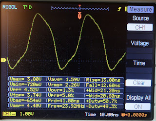
Oscilloscope Measurements
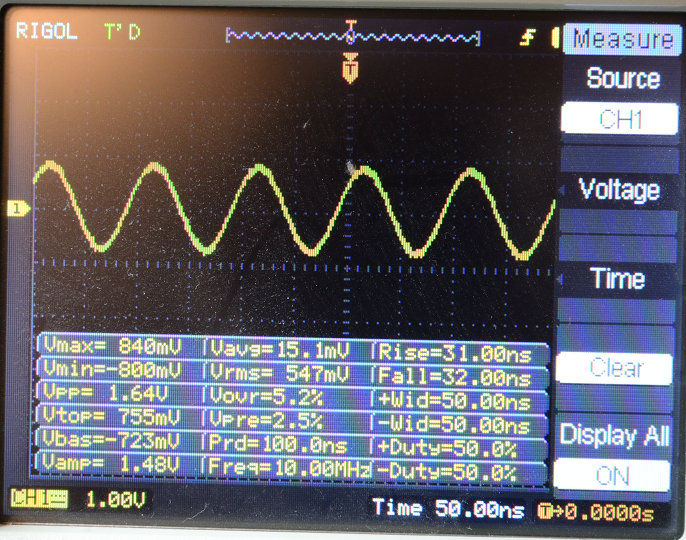
Scope snapshots from
X24MI,
X24MO and the 10 MHz signal for comparison. The amplifier output has some undershoot/overshoot but that's okay because it gets further filtered and cleaned up inside the SoC.
 |
| OSC24 input |
 |
| OSC24 output |
 |
| 10 MHz reference clock terminated to 50 Ω |
Clock Adapter Circuit
I made this simple adapter board to connect the clock. The purpose is to shift the signal upwards to be centered around roughly
Vcc/2 and to terminate it to roughly 50
Ω. The exact values are not hugely important. We just want to make sure we don't feed negative voltage into the amplifier input as that could potentially destroy the SoC.
 |
| Clock adapter schematic |
 |
| Clock Adapter on veroboard. Note that the 24 Mhz crystal has been removed from the board. |
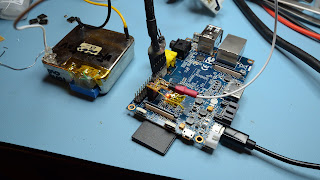 |
| System Powered up. |
|
Kernel Modifications
Next we must tell the kernel that we have changed the reference clock from 24 MHz to 10 MHz. In NetBSD this is controlled by
AWIN_REF_FREQ and we can accomplish what we need by changing a
single line in the source code.
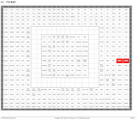
Here is a diff comparison of dmesg(8) output after changing this constant:
-cpu0 at mainbus0 core 0: 912 MHz Cortex-A7 r0p4 (Cortex V7A core)
+cpu0 at mainbus0 core 0: 380 MHz Cortex-A7 r0p4 (Cortex V7A core)
...
-armgtmr0 at armperiph0: ARMv7 Generic 64-bit Timer (24000 kHz)
+armgtmr0 at armperiph0: ARMv7 Generic 64-bit Timer (10000 kHz)
Unfortunately as a side effect our CPU speed has slowed down quite a bit. But 380 MHz was enough to run an NTP server in the 1990s so it should suffice now. Running slower is also more power efficient. :-)
Conclusion
Replacing the reference clock on this board was quite easy. It would be interesting to attempt the same operation on an x86 motherboard at some point. But it would probably be much harder to adjust all the clock multipliers on an x86 system.
In the next post I will attempt to calibrate the clock with NTP.


No comments:
Post a Comment